GT72R Data logger
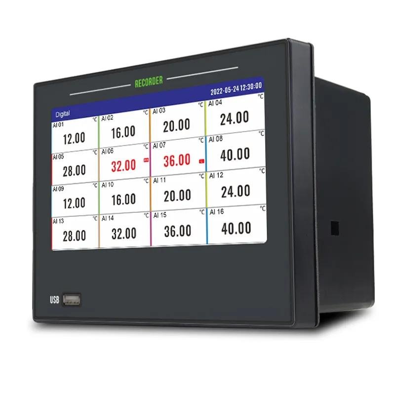
GT72R Paperless Recorder
Ideal for data monitoring and recording across multiple parameters including temperature, current, voltage, temperature & humidity, pressure, as well as signals from
Product Features
1. Product Performance
1.1 Measurement and Input Performance
Channel Configuration: Supports up to 32 universal isolated input channels, flexibly combined via 4 cards (input card, alarm card, transmission card). The standard configuration is 24 input channels + 16 alarm channels, with strong channel expandability.
Signal Compatibility: Compatible with current (4-20mA, 0-20mA, etc.), voltage (0-5V, 1-5V, etc.), thermocouple (12 types including K/S/B/J), and thermal resistance (4 types including Pt100/Cu50). Frequency signal is customizable, covering mainstream industrial standard signals.
Measurement Accuracy: Full signal type measurement accuracy up to ±0.2%F.S.; thermocouple measurement error ±2℃~±5℃ (depending on type), thermal resistance error ±0.5℃, sampling period 1 second, enabling accurate and efficient data collection.
Signal Processing: Supports 0.0-9.9s filtering to mitigate signal mutations; 0.0%-9.9% low-signal cutoff function to zero out signals below the set ratio, with strong anti-interference ability.
1.2 Storage and Recording Performance
Storage Capacity: 64MB memory, capable of storing 900,000 historical data records with cyclic overwrite; simultaneously records 256 alarm records, 256 power failure records, and 256 operation logs, ensuring complete data traceability.
Recording Interval: 12 optional levels from 1 second to 1 hour. With 32 channels and 1-second interval, it can record continuously for 10 days; for 1 channel and 1-second interval, the maximum recording duration is 320 days, adapting to different recording requirements.
Data Security: Historical data is not lost after power failure, and data in non-overlapping time periods remains intact after time adjustment; when channel signal or range is changed, historical data automatically adapts to the new range without confusion.
1.3 Output and Communication Performance
Output Functions: Up to 16 relay alarm outputs (250VAC 3A/30VDC 3A resistive load), up to 8 4-20mA transmission outputs (accuracy 0.2%, load ≤750Ω); 2 channels of 24VDC power distribution (total output current ≤60mA), supporting two-wire instrument power supply.
Communication Interfaces: Standard RS485 communication (Modbus RTU), Ethernet communication (Modbus TCP), optional RS485 acquisition interface (Modbus RTU); USB2.0 interface compatible with 32G large-capacity U disk for convenient data transfer.
Communication Parameters: RS485 baud rate optional from 9600-115200, parity modes including no parity/odd parity/even parity; Ethernet supports DHCP automatic acquisition or manual IP setting, port 502, default floating-point format 2143, adapting to industrial network environments.
1.4 Environmental and Structural Performance
Environmental Adaptability: Operating temperature -10~60℃, humidity 0~85%RH (non-condensing); strong EMC anti-interference ability, power supply burst pulse 2000V, signal burst pulse 1000V, ESD contact discharge 4000V/air discharge 8000V.
Structural Specifications: 7-inch color touch LCD screen (800×480 resolution), panel size 187×147mm, cutout size 138×138mm, panel-mounted installation, panel protection class IP65, weight 1100g, suitable for industrial indoor installation scenarios.
Power Supply Guarantee: Supports AC100-240V 50Hz or DC24VDC±10% power supply, power ≤20W, with 24VDC reverse connection protection for safe and stable power supply.
2. Core Selling Points
2.1 Multi-Channel Universal Input with Strong Adaptability
32 isolated input channels can flexibly access various signals such as current, voltage, and thermocouple without additional adapter modules, meeting industrial multi-parameter measurement needs in one stop and reducing equipment configuration costs.
Channels support Chinese Pinyin tag configuration (8 Chinese characters/16 characters), 0-3 adjustable decimal places, and optional open-circuit processing (maximum/minimum/hold), with flexible parameter configuration adapting to different monitoring scenarios.
2.2 Touch Operation + Multi-Form Display for High Usability
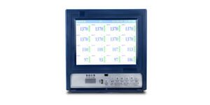
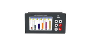
7-inch high-definition color screen with touch operation for sensitive response; supports 5 data display forms (digital display, bar graph, dashboard, real-time curve, historical curve), enabling intuitive data trend observation. Redundant channels can be hidden for convenient switching.
Built-in Chinese/English bilingual free switching, supporting configuration export/import, initial password 0000, and 6-level password hierarchical management. Non-professionals can be restricted from operation permissions, balancing security and usability.
2.3 Convenient Data Transfer and Printing for Strong Practicality
USB interface supports full/partial data transfer, files are automatically named “date + serial number” and stored in the PLR folder of the U disk. They can be opened and analyzed via upper computer software (PLR.EXE) without complex operations.
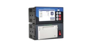
Standard micro printer interface (alternative to RS485 acquisition interface), supporting automatic/manual printing. Data, curve, or data+curve modes are optional, printing interval adjustable from 1 second to 480 minutes, and 3 custom titles (8 Chinese characters) are supported to meet on-site data retention needs.
2.4 Comprehensive Alarm Functions for Safety and Reliability
Supports 4 alarm types: upper upper limit, upper limit, lower limit, lower lower limit. Each channel can independently enable/disable alarms, with adjustable alarm delay (0-60 seconds) and hysteresis (0-99999), avoiding false alarms.
Alarm status is displayed in real time, and alarm records include channel, type, status, and time. Alarm cancellation records are retained for quick traceability of alarm causes; relay output can link external equipment to respond to abnormal conditions promptly.
3. Main Functions
3.1 Data Acquisition and Monitoring
Real-Time Acquisition: Synchronously collects data from 32 channels, displaying real-time measured values, units, and tags of each channel. Supports custom channel colors and free setting of display on/off, with a concise and clear interface.
Virtual Calculation: Supports channel virtual calculation configuration, allowing users to customize calculation formulas according to actual needs, expanding measurement functions and adapting to complex parameter calculation scenarios.
Accumulation Function: Each channel can independently enable/disable the accumulation function, supporting accumulation value clearing, adapting to the accumulation and statistics needs of parameters such as flow and energy consumption.
3.2 Historical Data Query and Management
Data Query: Queries historical curves by time range, supports channel hiding and channel scale switching. Historical data is displayed in numerical list or curve form for intuitive trend observation.
Record Query: Power failure records include power-off/on time and duration; operation logs record key operations such as configuration modification and time adjustment; alarm lists fully retain alarm and cancellation information, facilitating equipment maintenance.
Data Export: Quickly transfers historical data, alarm records, power failure records, and operation logs via USB U disk. Exported files are compatible with upper computer software, supporting further data analysis and report generation.
3.3 Alarm and Output Control
Alarm Configuration: Each channel can independently set alarm type, threshold, delay, and hysteresis, specifying the corresponding relay output contact. The relay acts with delay after alarm triggering to accurately control external equipment.
Transmission Output: Maps data from any input channel to 4-20mA transmission output, supporting Y=KX+B linear adjustment, adapting to PLC, DCS and other control systems to achieve closed-loop data control.
Printing Function: Automatic printing allows setting printing interval and channels, with an automatic printing icon displayed in the title bar; manual printing supports selecting any time range and specified channels, with flexible printing modes to meet on-site data recording needs.
3.4 System Configuration and Maintenance
System Settings: Supports date and time calibration, language switching, recording interval setting, automatic/manual thermocouple cold junction compensation, and cold junction value fine-tuning to ensure measurement accuracy.
Configuration Management: Supports input configuration (signal type, range, tag, etc.), alarm configuration, communication configuration, transmission configuration, and printing configuration. Configuration parameters can be exported to U disk for backup or imported from U disk for restoration, facilitating batch configuration.
Fault Diagnosis: Displays 、open circuits、over-limit alarms, intuitively indicating wiring faults or signal abnormalities; supports original signal debugging to quickly troubleshoot signal acquisition problems, enabling convenient maintenance.
Regarding more product technology
Jujea Ultrasonic Flowmeter Customer Case (RS485 Communication Fault Solution)
February 5, 2026
No Comments
Read More »
GT68PR Paper Recorder: A 6-Channel Integrated Printing Industrial Data Monitoring Terminal
January 4, 2026
No Comments
Read More »
GT80R Paperless Recorder: A High-Performance, Multi-Channel Industrial Data Management Terminal
January 4, 2026
No Comments
Read More »
GT68R Paperless Recorder: A 6-Channel Compact Industrial Data Monitoring Terminal
January 4, 2026
No Comments
Read More »

GT65R Paperless Recorder: A Compact, Efficient Data Terminal for Industrial Parameter Monitoring
January 4, 2026
No Comments
Read More »